
Fine-Tuning Tolerances for CNC Machined Parts
Table of Contents
CNC tolerances are where drawings are won and lost. Every feature on a machined part has a tolerance — how far the actual dimension may deviate from the nominal — and the cost curve is brutal: holding ±0.1 mm is cheap, ±0.01 mm costs several times more, and ±0.005 mm (the practical limit for standard CNC on aluminum) costs a premium. The buyers who control their tolerance spend are the ones who mark only the functional dimensions tight and leave the rest standard.
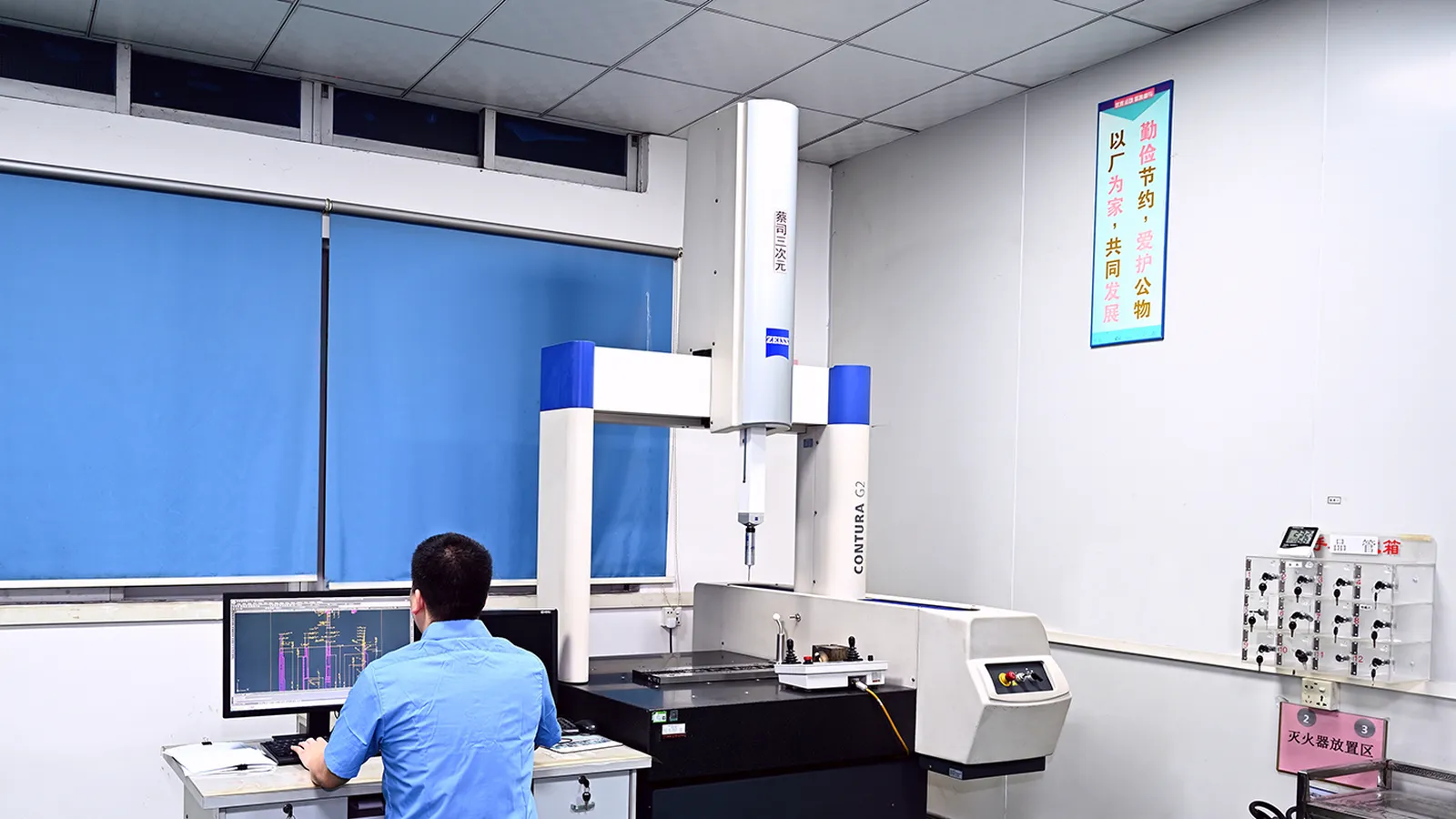
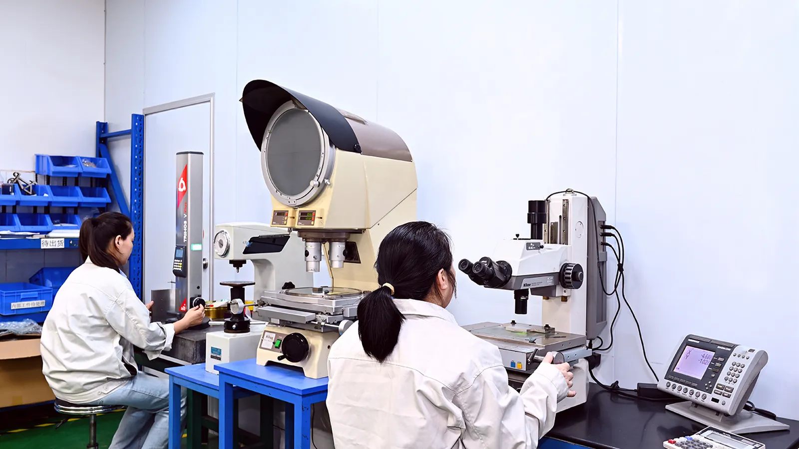
At MOLDITQUICK, the CNC machining line holds ±0.005 mm on critical features of aluminum, steel and engineering plastics, with a CMM verifying the first article and sampled lots. The realistic capability map: standard machining tolerance is ±0.1 mm (fine for most features), precision is ±0.02-0.05 mm (mating surfaces, bearings fits), and high-precision is ±0.005-0.01 mm (optical mounts, medical interfaces, die details) — and the tighter the tolerance, the more the price and lead time move.
What Drives the Cost of a Tight Tolerance
Three things happen when you tighten a tolerance. First, the process changes: roughing then finishing passes, smaller stepovers, slower feeds — the same part that machines in 30 minutes at ±0.1 mm takes 90 minutes at ±0.01 mm. Second, the machine and tooling matter: a rigid 5-axis mill with a proper workholding setup holds tenths; a worn machine or a flimsy fixture drifts. Third, inspection becomes part of the cost: every tight feature needs verification on the CMM, and thermal effects (the part grows and shrinks with shop temperature) have to be managed — which is why the shop temperature is controlled and critical parts are measured at a stabilized temperature.
The dimensional realities: holes below 3 mm should not be called out tighter than ±0.05 mm because drill wander sets the floor; flatness under 0.01 mm over 100 mm requires stress-relieved material and careful clamping; and tolerances on thin-walled parts are limited by deflection, not machine capability. The engineering rule: tolerance stack-ups should be calculated, not guessed — every ±0.05 mm on a drawing should trace to a function.
The Tolerance Hierarchy and How to Call It Out
The hierarchy from loose to tight: standard machining (un-toleranced dims, ±0.1 mm implied), precision (±0.02-0.05 mm — use for mating and clearance fits), high-precision (±0.005-0.01 mm — use only where function requires). On the drawing, use GD&T where the geometry matters — position, flatness, concentricity — rather than piling ±0.01 mm on every dimension. A position tolerance of Ø0.05 mm on a hole pattern is cheaper and more meaningful than ±0.02 mm on each coordinate, because it describes the actual assembly requirement.
Material affects what is achievable: aluminum 6061 machines beautifully to tenths; stainless 316 work-hardens and drifts more; plastics (POM, PEEK) move with temperature and moisture, so very tight tolerances on plastic parts need environmental control. In practice, we quote the tolerance plan with the price — the same DFM discipline our CNC vs injection molding guide applies to process selection. For market context, precision CNC services list ±0.005 mm capability as their standard premium tier (.
If you are not sure which tolerances are worth the money, send us the part and the assembly context. We will mark up the drawing with the tolerance plan — tight where it matters, standard everywhere else — and quote accordingly. Contact us to start.
One more practical note: tolerance should be specified as a range or class, not as a single optimistic number. The drawing standard matters — a drawing with a general tolerance block (for example "±0.1 mm unless noted") and a few tight call-outs is easier to quote, easier to inspect and cheaper than a drawing with ±0.02 mm stamped on every dimension. The suppliers who quote tight-everything drawings are quoting the risk they expect to eat. A clean tolerance scheme is the cheapest part of the design, and it is the first thing our engineers look for when a part comes in for review.
Need a quote? Contact us — upload your 3D file for a fast DFM review.
NEXT STEP
Ready to Start Your Project?
Send us your requirements — our team responds within 24 hours with pricing and lead time.
Written by
Ray ChanManufacturing Engineer · Custom Manufacturing Specialist. Ray helps global importers and integrators source factory-direct plastic parts and tooling.