
Uniform Wall Thickness: Avoiding Sink and Warp
Table of Contents
Uniform wall thickness is the single most important design rule in injection molding, and the most violated. When a molded part has thick and thin sections, the thick sections cool slower, shrink more and sink — leaving visible depressions on the opposite surface — while the thin sections fill later, pack less and may warp. The plastic does not "know" the design intent; it responds to cooling, which is a function of thickness. The fix is design discipline: hold the wall thickness constant within ±20-25% across the part, and use ribs, not thickness, for stiffness.
The recommended wall thickness depends on the material: ABS and PC run well at 1.5-3.5 mm; PP and PE at 1.0-3.5 mm; nylon (PA) at 1.0-3.0 mm; POM (acetal) at 1.5-3.0 mm; PC/ABS blends at 1.5-3.5 mm; and thin-wall designs in PC or ABS can go to 1.0-1.2 mm with careful gating. As a rule of thumb, a typical housing is 2.0-2.5 mm; a structural bracket with ribs can drop to 1.5 mm and gain stiffness. Our wall thickness guide has the full material-by-material table.
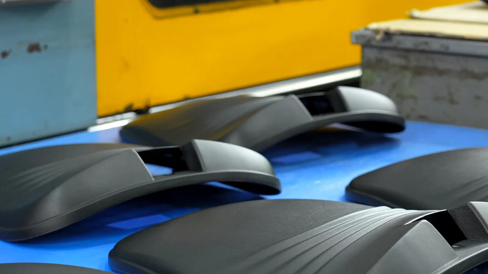
Sink Marks and Warpage: The Two Failure Modes
Sink marks are surface depressions caused by internal shrinkage in thick sections. When a 4 mm boss sits behind a 2.5 mm wall, the boss cools last, shrinks, and pulls the surface inward — the classic ghost on the class-A face. The fixes, in order of preference: core out the boss (make it a rib, not a solid cylinder — with a wall thickness of 60% of the nominal wall), or reduce the wall ratio. The rule: any local thickness above 1.5× the nominal wall is a sink risk, and the thickness ratio should stay below 1.5:1.
Warpage is the other failure mode — uneven shrinkage across the part pulls it out of flatness. Causes: non-uniform wall thickness, unbalanced gating, uneven cooling (differential mold temperature), and anisotropic shrinkage in glass-filled materials. The DFM fixes: uniform walls, balanced runners and gates, cooling channels that mirror the part geometry, and ribs to stiffen large flat areas. A large flat wall of 200×200 mm will warp with ribs; it will oil-can without them.
The Design Process That Prevents Both
The practical design sequence: set the nominal wall from the material table, keep it constant, replace solid bosses with cored ribs, gate at the thickest-feasible location, and run a mold-flow analysis before cutting steel. That last step is the difference between a first-shot success and a re-cut: mold-flow shows the sink and warp risk in the virtual mold, where a fix costs days, not weeks. Our DFM review at MOLDITQUICK checks wall thickness uniformity on every part before tooling — and our findings go straight into the tooling plan: gate, cooling and steel adjustments follow in days.
For metal parts the rule reverses: uniform wall thickness in die casting is also important (thick sections shrink and pull), and in CNC machining, uniform walls reduce deflection and vibration — the same discipline applies across processes, which is why we apply the DFM review uniformly. For market reference, design-for-manufacturing guides from full-service molders consistently list uniform wall thickness as the top DFM rule (.
If your part is showing sink marks, warpage or moldability problems, send us the model. We will review the wall-thickness map and show you the design changes that fix it — before you cut steel. Contact us to start.
Thickness transitions deserve their own rule: where the wall must change (a boss, a step, a flange), the transition should be gradual — a taper or a radius rather than a sharp step. A sudden thickness change creates a local cooling difference that shows as a sink line and concentrates stress. The guideline: transition over a length of at least 3× the thickness difference, and radius the inside corners. The same logic applies to ribs meeting walls: a fillet of 0.25-0.5× the wall at the rib base distributes the stress and hides the sink. These are small geometry details with outsized effects on first-shot success.
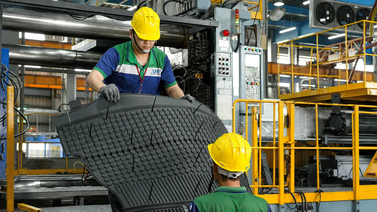
Need a quote? Contact us — upload your 3D file for a fast DFM review.
NEXT STEP
Ready to Start Your Project?
Send us your requirements — our team responds within 24 hours with pricing and lead time.
Written by
Ray ChanManufacturing Engineer · Custom Manufacturing Specialist. Ray helps global importers and integrators source factory-direct plastic parts and tooling.